- 2023-06-16
- 889
- 5 Comments
Mold parts processing knowledge
Mold accessories processing knowledge
1. The influence of CAD/CAM on high-speed machining
---- High-speed machining needs to meet many application conditions at the same time, once the parameter error will lead to total failure. Some of the key parameters are easy to define, such as high-quality machine tools with powerful CNC systems and high-precision spindles, high-rigidity and precisely balanced machine clamping, high-performance cutting tools, etc. Some parameters are not easy to define, but often due to the improper selection of these parameters, resulting in high-speed machining failure.
---- In addition to the above physical factors, the quality and proper application of CAD and CAM software are also major factors affecting high-speed machining. If the CNC program generated from the CAD/CAM system directly determines the conditions of processing, this is very straightforward. However, it is very difficult to point out in the CAD/CAM system what functions are required to ensure high quality high-speed machining results.
---- The following will analyze some of the important factors that affect the success or failure of high-speed machining when using CAD/CAM software.
The influence of CAD on high speed machining
---- In general, the direct impact of CAD on high-speed machining is not easy to see. Many people think that the CAD model is only used to define the shape of the part, and how to process the designed part is the responsibility of the CAM user and machining engineer. There's nothing wrong in theory, and in many cases, the CAD model doesn't really define the shape that needs to be machined. There are many reasons why the model is not suitable for high-speed machining, which are summarized as follows: Effect of accuracy
---- High machining precision, small heat distribution and high machining surface quality are the advantages of high-speed machining; But I saw a strange phenomenon: the tolerance used to build the part model was larger than the final machining tolerance.
---- Data exchange is the root cause of accuracy problems. Parts are usually designed by one CAD system and then transferred to another CAD system for supplementary design and machining preparation. Each time the data is transferred, the geometry needs to be converted from one format to another, and some conversions involve approximations to limit tolerances. Because these tolerances are cumulative, the part model must be designed with the tolerance of the part model set at least ten times less than the finishing tolerance.
---- Interchange formats such as IGES enable the system to convert between different geometric descriptions. Since the data sending system has access to the "master" data, it is best to let it do all the conversion work and do it through the IGES of the "flavouring" sending system. Flavouring will tell the system what type of entity is most likely to be used in the IGES file. Some systems offer a pre-defined IGES flavours menu, making it suitable for commonly used systems.
---- One way to reduce conversion problems is to use a direct interface. Direct interface let the system directly read another system's files, such as Delcam's PowerMILL has a direct interface for Catia, Pro/Engineer, Unigraphics and other mainstream systems.
---- Because of the simplicity of the Stereo lithography (STL) triangle format, it has become a preferred data interchange format for some companies. Some CAM systems can process STL files directly, including Delcam's PowerMILL. However, triangles of this format file are produced according to tolerances, and visible surfaces may appear on the machined surface. The tolerances used by the mainstream design system STL format are generally very large (0.1mm), and are hidden behind multiple options, which are easy to ignore. Therefore, the machining tolerance of STL file with low tolerance setting can improve the precision of machined surface.
Pruning effect
---- Most parts of a CAD system are made up of a "patchwork" of cut surfaces, such as a jacket, which is stitched together from multiple pieces of complex fabric. The boundary accuracy of these surfaces directly affects the quality of the resulting tool path.
---- for example, the top of a cone is a complete circle, and the flat top cover is hexagonal. The hexagonal plane may extend beyond the circle in some places at the top. If the scope is too large, the tool path will appear sharp points. In this case, knife marks are likely to appear on the finished surface. The impact of incomplete models
---- Many CAD users set their own shortcuts in order to shorten the modeling time of the model, which is often used, is to ignore the corner chamfering inside the base, but think that the tool with the right radius is directly processed. If this method is used, the tool must just cut into the sharp corner, so that the load of the tool is suddenly increased, which is 4.5 times when the tool is cutting in a straight line.
---- Some CAM systems can provide a solution, but it is best to avoid this phenomenon and ensure that the CAD model accurately represents the shape to be machined. Processing this type of round chamfer is best to use a smaller radius of the tool, in general, the radius of the tool is better than the geometric size of the round chamfer 70% or smaller, so that the corner of the cutting tool path more smooth, to avoid sudden turning of the tool. If machining with a small tool, the tool load is 3 times lower than cutting directly into the corner.
Can't process the effects of features
---- Although high-speed machining expands the range of features that can be milled directly, for models with particularly complex shapes, the fine parts must be machined using EDM. In addition, most parts have many holes that can be drilled directly out. If the CAD model used for machining includes these features, most CAM systems will attempt machining. The most typical result is that the tool path contains areas that you do not want to be milled, and if not treated, the tool must cut into holes or sharp corners during actual machining. CAM users need to spend a lot of time correcting errors to avoid reworking the discharge machining area and the hole area.
---- If possible, try to remove undesirable features from the CAD model used to generate the tool path. The exact method depends on the CAD system used. Some systems use the method of removing features, others by adding additional surfaces to cover.
The influence of CAM on high speed machining
---- After many years of research on high-speed machining, there is still a lack of clear and concise definition and explanation. The basic starting point of high-speed machining is to cut at high speed and low load, which cuts the material faster than low speed and high load cutting. Low load cutting means that cutting forces can be reduced, thus reducing vibration and deformation during the cutting process. High and hard materials can be cut with the right tool at high speed. High-speed cutting can use the cutting belt to remove most of the chips to reduce the thermal deformation of the parts.
---- The above advantages can only be realized under suitable processing conditions. If the processing conditions are not appropriate, it can affect the life of the tool, and even lead to more serious consequences.
High speed machining tool path
The limits of high-speed milling tool paths are listed in order of importance: The tool must not collide with the part The cutting load must be within the limit of the tool The residual material must not exceed the specified limit should avoid sudden changes in material removal rate The cutting speed and acceleration must be within the capacity of the machine The cutting direction (up/down milling) should be kept constant sudden changes in the cutting direction should be avoided to minimize airborne movement Cutting time should be kept to a minimum
---- In the actual tool path preparation process of parts, it is difficult to fully meet the above requirements. In fact, when processing complex shaped parts, you can only try to meet these requirements, and first meet the more important.
---- finishing causes the problem of knife marks in high-speed machining. Due to the limitations of the shape of the parts, if the cutting conditions are to be accommodated, visible knife marks will be left on the surface of the parts after processing, although they can be eliminated by polishing methods, but contrary to the original intention of using high-speed processing. After roughing and semi-finishing, CAM users have a variety of ways to modify the shape of the part, and the knife marks can be eliminated by subsequent finishing.
Programming ability
---- Good high-speed machining programs can be quickly executed on the machine tool, but take a long time and a lot of effort to produce. In the field of single piece processing in mold manufacturing, it is very common to wait for processing procedures to cause machine downtime. If this pressure is imposed on CAM users to generate tool paths faster, they will be forced to take shortcuts, and the program will not be economical and efficient. Even if the machine continues to operate, its processing speed has been greatly reduced.
---- It is not wise to use this method for high-speed machining. For the best high speed machining results, sufficient CAM capacity must be provided to obtain a high quality machining procedure and ensure full load operation of the machine. Therefore, the following should be noted
---- The use of CAM software with automatic high-speed machining function can reduce the workload of user optimization program;
---- Using CAM software for fast calculation of unovercut tool paths, batch processing function can leave the calculation of complex programs at night;
---- Use a high performance computer and update the configuration frequently to ensure adequate memory for high performance;
---- Ensure that each machine is adequately staffed with CAM programmers. Train machine operators to program directly on the shop floor to maximize their machining skills;
---- Ensure that operators are properly trained in high speed machining programming. Arrange the processing sequence
---- Except for the simplest parts, high-speed machining often involves multiple machining steps. In high-speed machining programming, the most important selection of the correct processing sequence, the following are some basic principles
---- When considering the geometry to be machined, the material to be excised should also be considered;
---- Minimize processing steps;
---- The use of continuous methods such as biased paths is usually better than balanced paths;
---- Avoid cutting vertically into the outside of the material;
---- In the critical area of the part, ensure that the finishing path of the different steps is not heavy. ; Otherwise there must be knife marks;
---- Try not to change the tool, use a single tool to finish the critical area. Tool setting errors often lead to tool marks on the machined surface after finishing.
---- Long tools are easy to wear, should try to use a short tool. If possible, consider reorienting parts and using short tools in areas that are difficult to process.
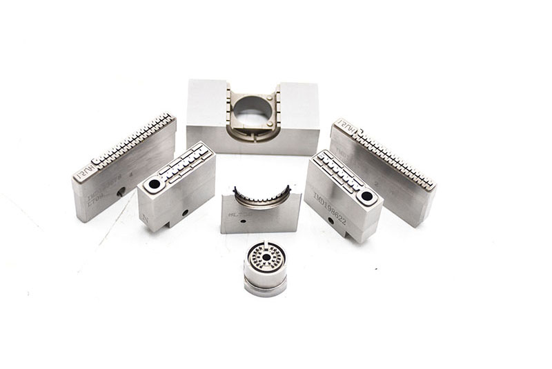
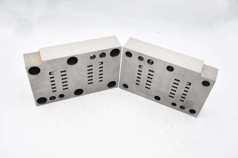
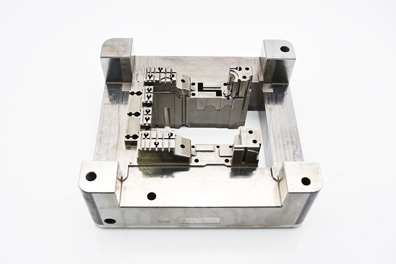
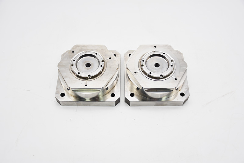
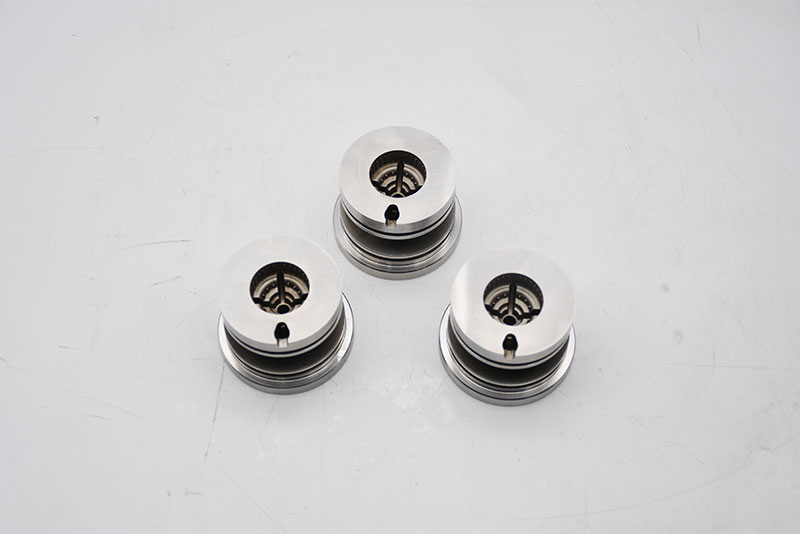
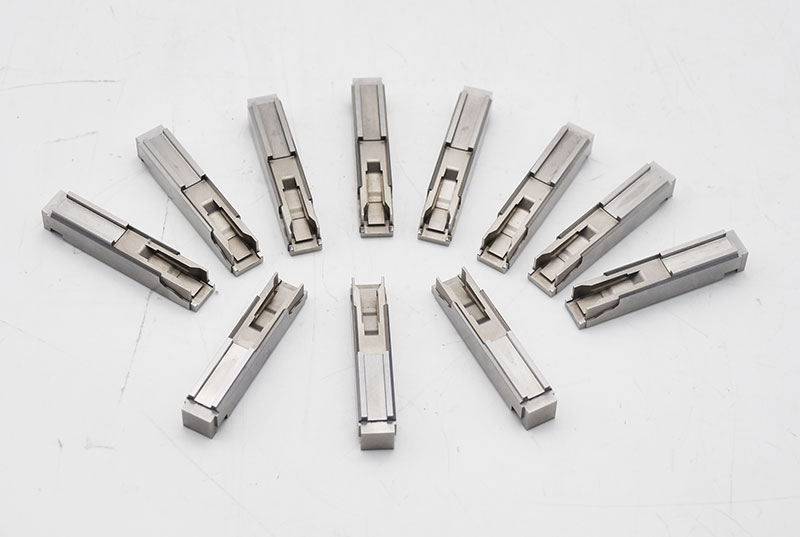
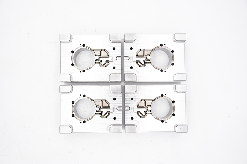
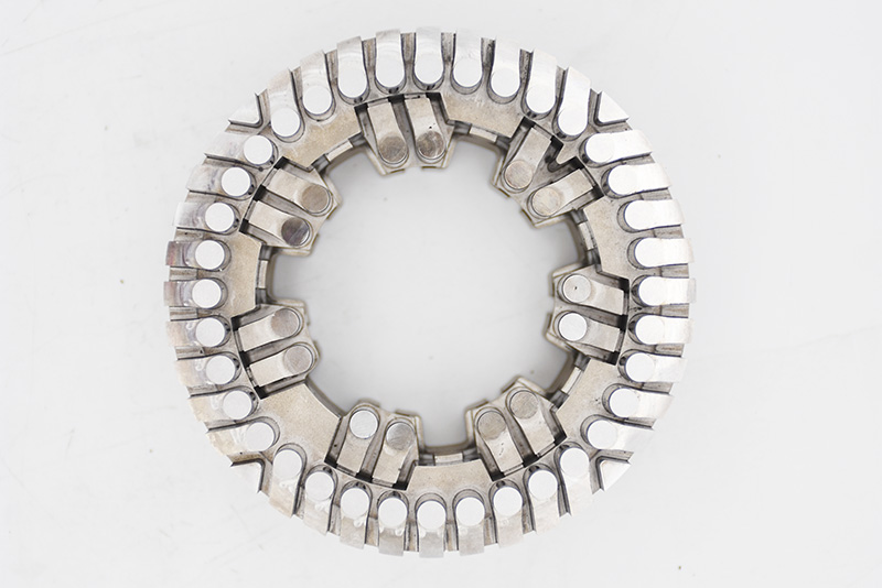
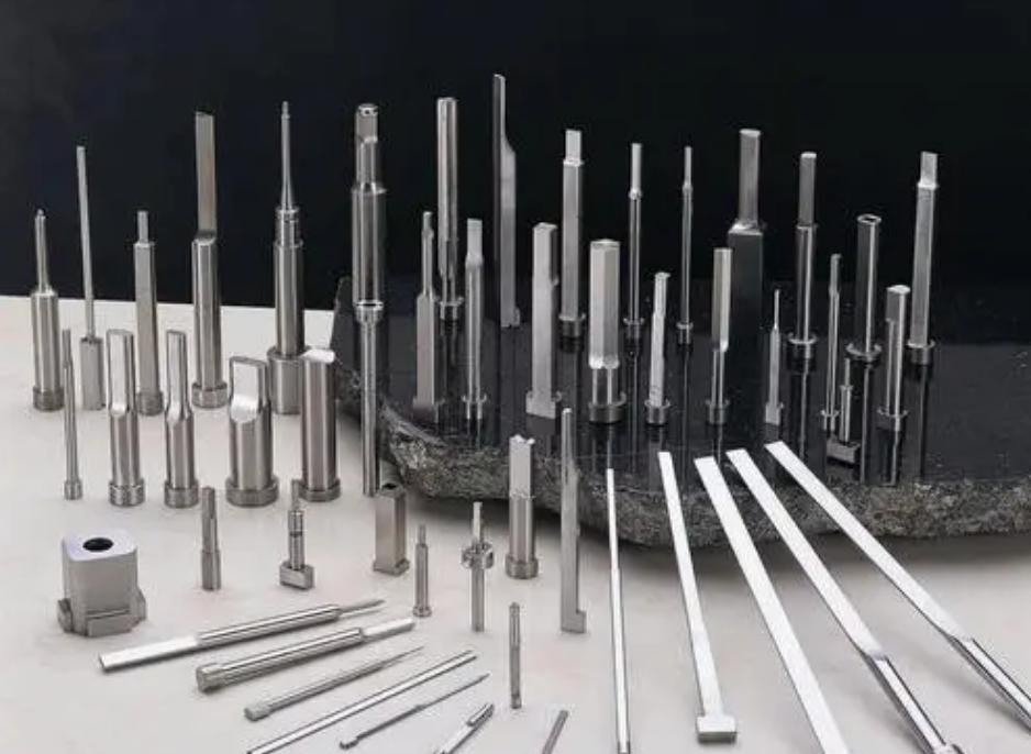
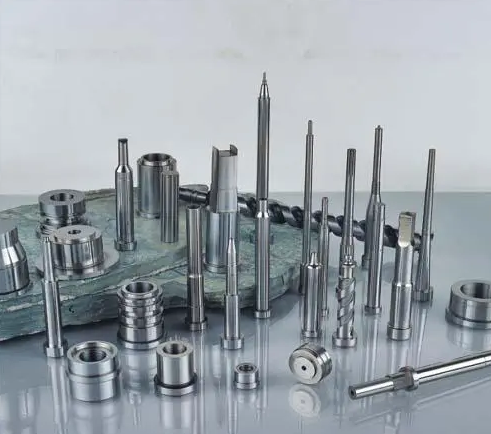
Dongguan Mingshang Mold Accessories Co., Ltd. specializes in manufacturing precision photoelectric shaft/screw electrode/pen model core/cosmetic parts/precision insert/core/bushing and SKH51 / SKD61 series cylinder thimble mold accessories, etc.
Products are widely used in optoelectronics/digital electronics/medical packaging equipment/pen/cosmetic packaging/electrical/automotive/mechanical motor shaft manufacturing and other fields.
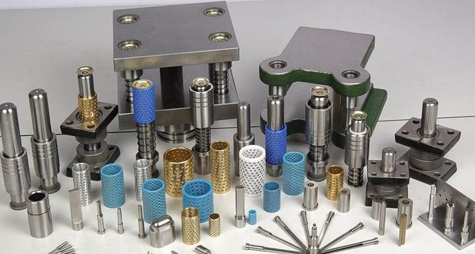
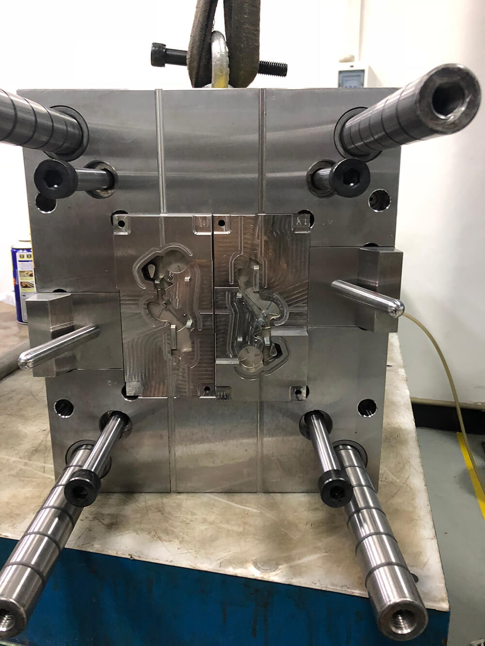
The company's products are non-standard mold parts processing, brass + graphite wear-resistant block processing, high force brass + graphite guide column guide sleeve processing, stainless steel guide column guide sleeve processing, all kinds of non-standard insert processing, precision plastic mold parts processing, metal stamping mold parts processing, die casting mold parts processing, daily cosmetics mold parts processing, Self-lubricating plate, self-lubricating guide rail, self-lubricating guide column guide sleeve, brass and graphite wear-resistant block processing, high force brass and stone ink wear-resistant block processing, oil steel and graphite wear-resistant block processing, cast iron and graphite wear-resistant block processing, precision tooling and precision automatic mechanical parts and many other fields, to provide customers with precision mold accessories processing comprehensive solutions.
The main products are:
1. Pen/cosmetics/packaging products: pen model core/pen cap accessories/pen core screw inserts/lipstick series/spray mold;
2. Medical packaging equipment products: injector core/needle core (assembly)/test tube core/medical packaging bottle cap screw core withdrawal/wire-drawn cap core and push plate sleeve; Mascara top and bottom cover, front and back mold core;
3. Photoelectric/digital electronic products: precision photoelectric tooth shaft/precision insert/core/bushing/precision positioning, accuracy tolerance is generally controlled within 0.002-0.005, all attached test report for customer inspection;
4. Home appliances, automotive machinery products: self-moistening wear-resistant block (high force brass and graphite)/oil-free self-moistening guide sleeve, movable core components (inclined top seat)/guide post auxiliary/positioning column, etc.;
5. Precision stamping die parts: Non-standard punch, punch, punch, tungsten steel punch, CNC punch, cemented carbide punch, ASP-23 punch, powder high speed steel punch, SKH51 punch, SKD11 punch, DC53 punch, female punch, female shaped punch, guide punch, guide pin, turning hole Punching needle, forming punch, oval punch, square punch, hex punch, shaped punch and other customized;
6. Bushing, die insert, lower die, CNC die, shaped bushing, contour set, float pin, cross pin float pin, guide float pin, tungsten steel punch and other standard and non-standard precision stamping die accessories customized;
7. Guide pin, positioning pin, stop height column, limit column and other standard and non-standard customized;
8. SKH51 thimble, SKD61 thimble, bracket needle, flat thimble, ejector pin, cylinder needle, push tube, imported material thimble and cylinder non-standard;
9. Customized cold-stamping die accessories such as guide post guide sleeve, GP auxiliary guide post, GP auxiliary guide sleeve, SRP ball guide post guide sleeve, SGP sliding guide post guide sleeve, discharge plate guide post guide sleeve, TRP removable guide post guide sleeve, independent guide post, non-standard guide post guide sleeve;
10. Drill die, beryllium bronze die, diamond pin, positioning pin, countersunk pin, top pin, pin shaft, connecting screw, block shaft, block sleeve, bushing and other machine parts customized;
Related Posts
- Precision Irrigation mold cavity and spare parts
- zefu-mold
- 1014

